Collection and processing of contactless smart card signals
0 Preface
A smart card is an integrated circuit card (IC), which encapsulates one or more integrated circuits in a card and has functions such as information storage, logic judgment, and calculation. Smart cards are divided into contact smart cards, contactless smart cards, and dual interface cards (contact and non-contact). The contact smart card reads and writes data by contacting the contacts of the read/write device with the contacts on the card. The contactless smart card combines radio frequency identification technology and IC card technology to complete data read and write operations through the transmission of radio waves. The contactless smart card has the characteristics of convenient use, short time when the card is swiped, and high reliability.
1 Wiegand communication protocol
Most contactless smart cards use the Wiegand protocol. The Wiegand protocol is an internationally uniform standard with many formats. The most commonly used standard is the 26-bi format, which is an open format that is open to all HID users.
The standard Wiegand output consists of a 26-bit binary number that is output on the reader's Wiegand output lines D0, D1. The meaning of each bit is as follows:
![]()
The first bit is an even parity bit of 2-13 bits;
The 2nd-9th bit corresponds to the lower 8 bits of the electronic card HID code;
The 26th digit is the PID number of the 14-25 corresponding electronic card;
The HID number is the Hidden ID Code implied code, and the PID number is the Public ID Code public code. The PID is easily found in the output of the reader, but the HID is partially or completely hidden in the output of the reader. HID is a very important number that exists not only in the card but also in the card reader.
2 Wiegand26 interface design
The Wiegand26 interface usually consists of three lines, which are Data0, Data1, and Signal Ground, which are responsible for transmitting Wiegand signals. DO and D1 maintain a high level of +5V when there is no data output.
If the output is 0, then Do is pulled low for a while; if the output is 1, D1 is pulled low for a while. The minimum separation between the two electronic Kawegen outputs is 0.25 seconds.
2.1 hardware interface circuit
DataO and Datal have a total of 26 low-level pulses, each of which represents a bit of data. The first bit is the even parity bit of 1-13 bit, the 26th bit is the odd parity bit of 14-26 bit, and the Bit2-Bit25 is 6 DIGITS (one DIGITS every 4 bits) representing the last six of the card number. Number of digits. The implementation process of signal processing can adopt the relay method, and its interface circuit is shown in Figure 1:
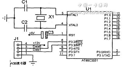
Figure 1 microcontroller interface circuit
2.2 data processing software design
The data processing software consists of a main program, an interrupt program, and several subroutines. The main program mainly completes the control of the workflow, and the program flow chart is shown in Figure 2. The interrupt program includes the INT0 interrupt program and the INT1 interrupt program, as shown in Figure 3.
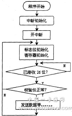
Figure 2 main program flow chart
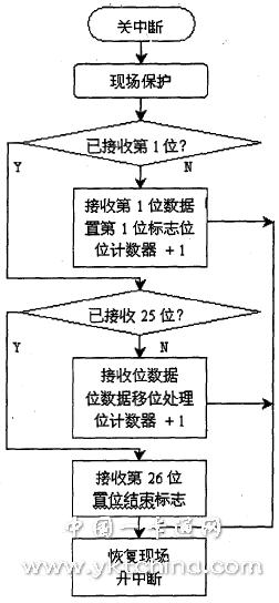
Figure 3 INTO (INT1) flow chart
references
1. He Limin, Selected Application of Single Chip Microcomputer (8) [M]. Beijing: Beijing University of Aeronautics and Astronautics Press, 2000.
2, Yu Yongquan, Wang Minghui, Huang Ying. The application of single chip microcomputer in control system Beijing: Electronic Industry Press, 2003.
About the author: Xie Ruizhen (196s one), male, Han nationality, the main research direction: computer security and information management.
Ningbo XISXI E-commerce Co., Ltd , https://www.petspetsaccessories.com